| Moderated by: chrisbet, |
|
|
| MC-36 remote with damaged leadAny suggestions for tempoary (or permanent) repair | Rate Topic |
| Author | Post |
|---|
| Posted by Robert: Mon Aug 26th, 2019 15:34 | 1st Post |
| I got an MC36 remote a while back, I knew it was damaged but had forgotten about it until this evening. Ideally the remote needs opening up and the wires need shortening and reconnecting to the PCB inside. I can't handle fine soldering anymore, not that I have ever been much good at really fine pcb work. I wondered about using self amagamating tape wound tightly around the ferule and the first inch or so of the cable but it seems like a bit of a lashup on a nice instrument. Any suggestions for a decent repair. It works just fine but it won't last long like that and moisture could get into the MC36 itself via the cable. You get quite a bit of condensation at night. 
____________________ Robert. |
| Posted by chrisbet: Mon Aug 26th, 2019 15:44 | 2nd Post |
| How big is the plug on the end - could you use some heat shrink tubing?
____________________ If it is broken it was probably me .... |
| Posted by Robert: Mon Aug 26th, 2019 16:19 | 3rd Post |
| Unfortunately it's an angled ten pin plug with integral locking nut. relatively bulky, I don't think any heat shrink would seal onto the cable outer which won't be any bigger than 6mm. I suppose I could build the cable up with some tape and then use heatshrink. 4X might do it, preferably with glue lined tube.
____________________ Robert. |
| Posted by chrisbet: Mon Aug 26th, 2019 17:48 | 4th Post |
| Another thought - if there is room inside the case, could the cable be pulled through to the good cover and fixed with a little silicone sealant?
____________________ If it is broken it was probably me .... |
| Posted by Robert: Mon Aug 26th, 2019 20:59 | 5th Post |
| Fresh back from using ot for the first time, it's wonderful, works like a dream. Made six minute exposures for the first time with digital. The D800 handles it perfectly. Thanks for the suggestion Chris, I will try splitting it tomorrow, see what's possible. I just taped it up for now. It's well worth restoring to good health.
____________________ Robert. |
| Posted by jk: Tue Aug 27th, 2019 07:19 | 6th Post |
| Robert, Some suggestions for a repair. 1. You can get some large heat shrink cable, split it lengthwise and make sure it overlaps so it double covers the area. This will still leave you with a weak point at the entrance into the enclosure. You might be able to insert some heat shrink over the cable and into the housing. This would give you better physical strength. 2. Straighten out the cable then set it in potting compound or use Araldite around the area. You will need to make it so it does NOT flex as eventually the individual strands will break if they are subjected to multiple flexing. You might need to glue to the case to make for greater strength. 3. It might be possible to open the unit and pull the cable through into the enclosure then reseal the MC-36. You will need to check that these extra cables will fit inside. **** This would be my preferred solution. **** You can use some thick rubber solution or small amount of something like Evostik to seal it. 4. It might be possible to open the unit and resolder the cable after trimming but I would NOT suggest that as a first way forward unless you feel happy at soldering fine wires onto a very small circuitboard. I would have taken this on 10 years ago but my eyes are not as good at 1m from subject as before. Using reading glasses dont work, as well as eyes without glasses, as you need to change focus through the vertical plane which will result with you needing to bob your head around. DO NOT USE Silicone sealant as it contains acetic acid that will rot the circuitboard and cable.
____________________ Still learning after all these years! https://nikondslr.uk/gallery_view.php?user=2&folderid=none |
| Posted by Robert: Tue Aug 27th, 2019 07:29 | 7th Post |
| Have opened up the MC-36, it's very well made, seems to be dated 7th Dec, 2016, or possibly 16th Dec, 2007? The American format back to front dates are a nuisance when they are showing dates which could be either. I'm not comfortable with the idea of re-soldering the connections, there are only 4 actual connections to the PCB but in a very tight space. The yellow, white and purple are the signal wires, the separate one behind, is the bonded earth/0V connection. I have tried with shrink wrap to get my largest piece over the plug but there is no chance, also I doubt if the shrinkage would be sufficient to grip the lead. There might be scope to cut back the sheath and make a coil of the spare conductor length above the main chip, not something I feel I could manage without damaging something. These devices are best part of £200, this was almost given to me. It works perfectly, I'm reluctant to do anything which may compromise that. 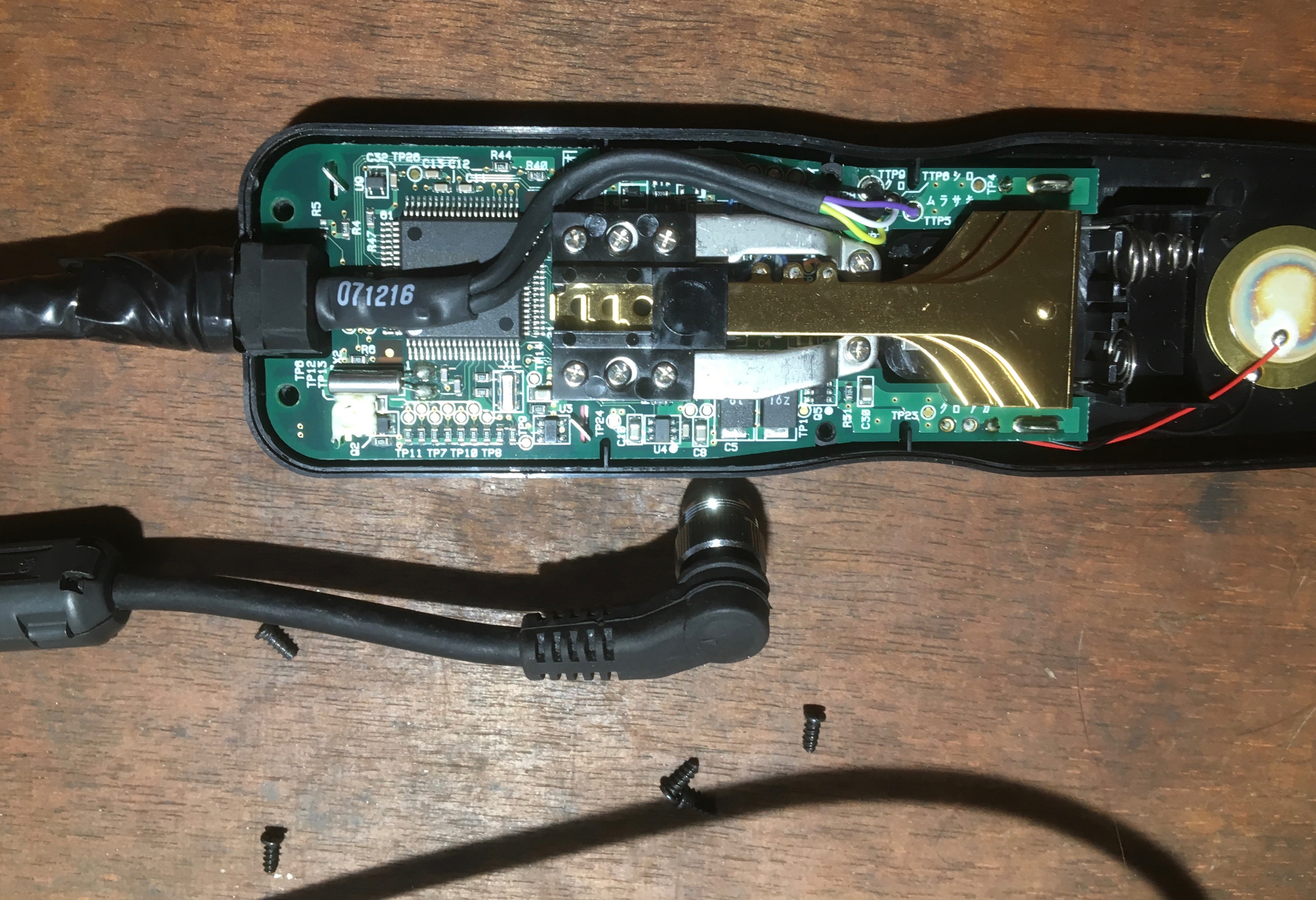
____________________ Robert. |
| Posted by jk: Tue Aug 27th, 2019 07:33 | 8th Post |
| OK now I can see the innards. My no3 option is the best way IMHO. Will the cable pull through the gland into the enclosure. BTW. You can get MC-36 for £30 on ebay. There are also clones from Hahnel and other non-OEM suppliers that cost a similar price. https://www.ebay.co.uk/itm/Nikon-MC-36A-Mutil-Function-Remote-Shutter-Cord-Control-For-Select-Nikon-DSLRs/333151281199?hash=item4d915d202f:g:nxIAAOSwz7JZiZPd https://www.ebay.co.uk/itm/Cable-shutter-release-with-timer-Nikon-MC-36A-MC-36-MC-30-Remote-Shutter-Release/254259450438?hash=item3b330b5246:g:sPAAAOSw3nhc~hB6
____________________ Still learning after all these years! https://nikondslr.uk/gallery_view.php?user=2&folderid=none |
| Posted by Robert: Tue Aug 27th, 2019 07:37 | 9th Post |
Stop! Wait, if I cut the leads with plenty slack, then jointed the individual conductors well clear of the PCB and stagger the joints so there isn't a big bundle in one place, I think I could do it... Mmmmm... Will sit on it, no need for hasty action I might regret... Thanks for the suggestions JK, I agree some variation of your #3 is best, there isn't a lot of room in there. It works perfectly, am reluctant to spoil it. My eyes are similar, but probably more of a problem for something like this, my fine motor dexterity has never been good but rheumatics and arthritis make it very difficult to do fine work nowadays.
____________________ Robert. |
| Posted by jk: Tue Aug 27th, 2019 07:38 | 10th Post |
Robert wrote:Stop! Wait, if I cut the leads with plenty slack, then jointed the individual conductors well clear of the PCB and stagger the joints so there isn't a big bundle in one place, I think I could do it... Mmmmm...Yes that would work. Messy but works.
____________________ Still learning after all these years! https://nikondslr.uk/gallery_view.php?user=2&folderid=none |
| Posted by jk: Tue Aug 27th, 2019 15:40 | 11th Post |
| Purple, white, green, yellow in one of the two sub-leads to circuit board. What colours in the other sub-lead? This diagram shows the pinouts for the 10 pin plug. 
____________________ Still learning after all these years! https://nikondslr.uk/gallery_view.php?user=2&folderid=none |
| Posted by GeoffR: Wed Aug 28th, 2019 06:40 | 12th Post |
| Robert, that looks to be a fairly simple soldering job. The wires terminate on holes through the PCB so shouldn't tax a competent technician. I'm 300 miles away or I would happily do it for you but I suspect there will be someone local who can do it, TV repair shop, if they still exist?
|
| Posted by Robert: Wed Aug 28th, 2019 06:46 | 13th Post |
| I added to my one but last post while you were making yours I think... Thanks for the diagram JK, the MC-36 is back together for now. When I open it up again I will make better photos. I think I will go with my version of #3, although it's a bit messy, it allows me to add shrink wrap to the lead as it enters the ferrule, that is a weak point as is confirmed by the existing damage. It will generally be used in cold conditions so the lead sheath is likely to crack up again. These lead inlets seem to be a source of problems on many electrical items. I need to be 'in the mood' to tackle these tasks with no distractions. Tricky job at best of times. But in my opinion it's well worth the effort. I was intending to get a Foolography smart phone remote 'Unleashed' module, which can give extended control like automating the 'Holy Grail' time-lapse control which can adjust all the exposure parameters. This is essential to allow full exposure control for 24 Hr, day/night, time-lapse photography, apart form the very latest Nikon models I think the D850 and maybe the Z's can do this but I'm not sure how well. For now the MC-36 gives me a lot more range for my night time photography. I need to understand how to get good exposures with these longer shutter speeds, reducing the ISO and closing the aperture, makes it a whole different game. A lot of testing and experimenting, wishing for plenty of cloud free, clear nights ahead.
____________________ Robert. |
| Posted by Robert: Wed Aug 28th, 2019 06:59 | 14th Post |
GeoffR wrote:Robert, that looks to be a fairly simple soldering job. The wires terminate on holes through the PCB so shouldn't tax a competent technician. I'm 300 miles away or I would happily do it for you but I suspect there will be someone local who can do it, TV repair shop, if they still exist?Thanks Geoff, I know for a competent tech it's dead easy, I have a friend, ex RAF senior tech who could do it but he lives in North Wales, just down the road from Jeff. The nearest actual repair shop I can find is in Carlisle, best part of 100 miles. I am sure there would be some very skilled hands just down the road in Barrow at BAE Systems, but I don't know any, although I do have some contacts... I will ask around. I was reminded of my lack of dexterity just now when I tried to unlock the front door to receive a parcel from the postman (my new ISP's router), it took me several goes to get the key in the lock! Doddery old bugger! LOL
____________________ Robert. |
| This is topic ID = 1729 | ||
| Nikon DSLR Forums > Camera and Lens Forums > Camera Accessories and Extras. > MC-36 remote with damaged lead | Top | |
Users viewing this topic |
||
Current theme is Blue
| A small amount of member data is captured and held in an attempt to reduce spammers and to manage users. This site also uses cookies to ensure ease of use. In order to comply with new DPR regulations you are required to agree/disagree with this process. If you do not agree then please email the Admins using info@nikondsl.uk Thank you. |
Hosted by Octarine Services
Copyright © 2008-2024 Data 1 Systems
Page processed in 0.1290 seconds (66% database + 34% PHP). 102 queries executed.
Copyright © 2008-2024 Data 1 Systems
Page processed in 0.1290 seconds (66% database + 34% PHP). 102 queries executed.